


Views: 0 Author: Site Editor Publish Time: 2026-09-24 Origin: Site


Poorly configured exterior lighting creates immediate operational and residential headaches. It wastes expensive electricity by running unnecessarily during daylight hours. It prompts angry neighbor complaints regarding intrusive nighttime glare. Most critically, erratic lighting compromises your secure perimeters, leaving vulnerable blind spots. Setting a proper schedule solves these overlapping issues effectively.
However, the exact configuration process depends heavily on your underlying hardware architecture. You might have an integrated motion sensor dial mounted directly on the fixture. You could be operating an inline mechanical wall switch inside the building. Alternatively, you may rely on a modern smart relay system communicating over Wi-Fi. We will clarify these technical distinctions immediately.
This guide sets clear expectations for mastering your exterior illumination. You will learn standard calibration procedures for basic integrated sensors. We cover advanced dual-mode setups to handle complex scheduling requirements. Finally, you will discover strict evaluation criteria for upgrading existing lighting controls successfully.
Standard flood light sensors require a three-point calibration: Time (duration), Sens (range), and Lux (daylight sensitivity).
Advanced dual-mode configurations (e.g., schedule-based constant ON, reverting to motion-only) require specific smart relays or programmable wall switches, not just integrated fixtures.
Upgrading controls requires evaluating weatherproofing (IP rating), load capacity (especially when integrating temporary high-draw fixtures like an LED Work Light), and smart ecosystem compatibility.
Electrical code compliance and safety protocols are non-negotiable when modifying hardwired exterior timer circuits.
Before adjusting any dials or replacing hardware, you must identify your current control system. Different architectures dictate completely different calibration methods. We divide these systems into four primary categories.
Most residential and light-commercial fixtures use Passive Infrared (PIR) sensors. These sensors detect heat signatures moving across their field of view. The "timers" on these integrated units do not schedule specific hours of operation. Instead, they dictate how long the illumination remains active after motion is detected. You typically find these controls located on the bottom of the sensor housing.
Programmable wall switches replace standard toggle switches inside your building. They provide an excellent solution for scheduling constant power to non-sensor fixtures. You wire the switch directly into the circuit. You then program specific on and off times. This approach works best when you need guaranteed illumination during specific operating hours, regardless of physical movement in the area.
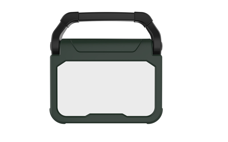
Sometimes you need temporary exterior lighting. Construction sites, event spaces, and temporary security zones often rely on heavy-duty plug-in timers. For example, you might secure a remote equipment yard by connecting a rugged LED Work Light to an automated outdoor timer. This ensures the site remains lit overnight without requiring hardwired installation. These timers simply plug into a standard GFCI exterior outlet and feature mechanical pins or basic digital displays.
Enterprise facilities and advanced prosumers usually adopt smart relays. You install these discrete modules behind standard wall switches or directly at the junction box. They connect to your local wireless network. Smart controllers allow remote scheduling via smartphone applications. They support advanced geofencing algorithms. They also enable dual-mode operations, combining strict time schedules with localized motion triggers.
Control Architecture Comparison
Architecture Type | Primary Use Case | Scheduling Capability |
|---|---|---|
Integrated PIR Sensor | Basic perimeter security | Post-motion duration only |
Programmable Wall Switch | Guaranteed operating hours | Fixed daily schedules |
Outdoor Plug-in Timer | Temporary sites / Job sites | Mechanical daily intervals |
Smart Relay System | Complex automated zoning | Dynamic / App-controlled |
Calibrating an integrated exterior sensor requires a systematic approach. Guesswork leads to frustrating false alarms and dark zones. Follow this proven framework to optimize your hardware.
Safety comes first. Never perform adjustments while standing on a ladder near live electrical components if the housing is open or damaged. You must isolate power at the main breaker panel before attempting physical repairs or wiring inspections. Even when just tweaking exterior dials, flip the indoor wall switch to the OFF position first. Gather a small flathead screwdriver. Most sensor dials require a precision tool for accurate tuning.
The "Time" dial controls duration. It dictates how many minutes the fixture supplies power after the sensor stops detecting motion. Standard intervals generally range from 1 minute up to 20 minutes.
Best Practices: Choose a 5-minute interval for standard driveways and walkways. This provides ample time for someone to reach the door. It also minimizes energy waste. Setting the timer to 20 minutes often results in unnecessary power consumption, especially if local wildlife frequently triggers the system.
The "Sens" dial determines how far out the PIR sensor detects heat movement. Setting this too high causes passing cars to trigger your lights. Setting it too low renders the system useless.
Use the "walk test" framework to calibrate this dial.
Turn the Lux dial to the daylight setting (usually a sun icon) so the light functions during the day.
Turn the Time dial to the lowest setting (e.g., 10 seconds).
Walk across the targeted detection zone.
Note exactly where the Flood Light turns on.
Adjust the Sens dial up or down. Repeat the walk test until the detection boundary aligns perfectly with your property line.
The "Lux" dial controls the internal photocell. This determines how dark the surrounding environment must be before the motion sensor becomes active. Proper calibration prevents daytime misfires.
Common Mistake: Many users set the Lux dial perfectly in the middle. Consequently, the lights turn on during overcast afternoons. To fix this, wait until dusk reaches your preferred level of darkness. Turn the Lux dial slowly toward the "moon" icon until the light clicks on. Leave it exactly at that threshold.
Modern security protocols often demand flexible lighting states. Basic sensors struggle to accommodate nuanced operational schedules.
Consider a highly common commercial and residential requirement. You want the exterior lights to remain constantly illuminated from 7 PM to 10 PM to welcome evening visitors or late-shift workers. After 10 PM, you want the lights to switch into motion-only mode until dawn. This approach balances welcoming aesthetics with late-night energy conservation.
You must understand one crucial reality. Standard off-the-shelf integrated fixtures cannot perform this dual-mode scheduling natively. A basic PIR fixture only knows how to trigger upon motion. If you connect it to a standard programmable wall timer, the timer simply cuts the power at 10 PM. Once the timer cuts the power, the motion sensor loses its electricity. It becomes completely inactive. You cannot have both features using basic consumer hardware alone.
Achieving true dual-mode operation requires bypassing internal sensor limits. You pair a programmable smart switch with a PIR-equipped fixture. You wire the fixture so the motion sensor and the smart switch operate in parallel. When the smart switch activates at 7 PM, it bypasses the sensor and feeds constant power to the bulbs. At 10 PM, the smart switch shuts off. The power load drops back entirely onto the motion sensor circuit. The sensor then resumes its normal dusk-to-dawn standby monitoring. This requires specific wiring configurations, usually necessitating an independent "switched hot" and "constant hot" wire.
Many users accidentally force their systems into constant-ON mode. This happens due to a hardwired legacy feature called manual override. Toggling a standard light switch off and on rapidly (usually within two seconds) bypasses the PIR sensor module. This forces the light to stay illuminated indefinitely.
If your lights refuse to turn off, you likely triggered this glitch. You reset the system by turning the wall switch OFF. Wait at least ten full seconds to allow the internal capacitors to drain. Turn the switch back ON. The sensor will reboot into standard auto-motion mode.
When basic mechanical dials fail to meet your operational demands, you must upgrade your control hardware. Evaluate replacement components across four critical dimensions to ensure reliable performance.
Every timer switch features a maximum wattage rating. You cannot overload the internal relay. Before daisy-chaining multiple exterior fixtures to a single smart switch, you must calculate the total load. Add up the wattage of every bulb on the circuit. Ensure the total falls at least 20% below the timer's maximum limit. For example, if you plan to integrate a high-draw temporary setup using a heavy-duty LED Work Light, verify the specific amperage demands. Exceeding capacity causes switch failure and poses severe fire risks.
Exterior timer enclosures face harsh environmental abuse. You must evaluate the Ingress Protection (IP) ratings carefully.
IP Rating Evaluation Guide
IP Rating | Protection Level | Appropriate Use Case |
|---|---|---|
IP44 | Splash resistant | Covered porches, deep eaves |
IP65 | Water jet resistant | Exposed exterior walls |
IP67 | Temporary submersion | Ground-level landscaping |
Always install in-use weatherproof covers (often called "bubble covers") over exterior digital timers. These covers comply with electrical codes by protecting the outlet even while a cord remains plugged in.
Standard mechanical dial timers require constant manual adjustment. As the seasons change, the sun sets earlier or later. You end up wasting energy or suffering dark periods. Upgrade to astronomic timers. Astronomic timers use geographical coordinates to automatically adjust for local sunrise and sunset times every single day. They calculate seasonal shifts perfectly. They eliminate the need for manual seasonal recalibrations.
Smart timers introduce cybersecurity variables. When integrating Wi-Fi-enabled lighting controllers, maintain strict network hygiene. IoT devices typically require a 2.4GHz network band. They struggle with modern 5GHz bands.
Best Practice: Create a dedicated, segmented guest network solely for your smart relays. This isolates your exterior lighting hardware from your personal computers and sensitive data servers. Keep the device firmware updated automatically to patch known vulnerabilities.
Modifying exterior electrical circuits introduces significant safety risks. You must approach installation with a clear understanding of your own limitations.
Replacing a simple integrated sensor housing usually falls within DIY territory. However, upgrading the wall controls requires a licensed electrician under specific conditions. Apply this shortlisting logic. If you open your switch box and do not find a neutral wire (typically a bundle of white wires tucked in the back), stop immediately. Most modern smart timers require a dedicated neutral wire to maintain standby power. Additionally, if you need to upgrade the circuit's overall amp capacity to support additional fixtures, hire a professional.
Older exterior junction boxes present hidden dangers. Reversed polarity occurs frequently in legacy wiring. This means the hot wire connects where the neutral should go. While the light might still function, the housing itself could become energized. This poses a lethal shock hazard. Inadequate grounding represents another massive risk. Always ensure the bare copper or green ground wire connects securely to the fixture mounting bracket.
Placement dictates reliability. An improperly placed sensor fails constantly. Keep PIR sensors away from HVAC exhaust vents. The sudden blast of warm air triggers false alarms immediately. Avoid aiming sensors directly at highly reflective surfaces like swimming pools or large glass windows. Sunlight reflecting off water confuses the photocell, causing erratic daytime cycling.
The right timer configuration creates a secure, efficient environment. Proper calibration prevents energy waste and eliminates frustrating false triggers. You maintain strong security perimeters without annoying your neighbors.
Begin by auditing your current exterior fixtures. Identify whether you operate mechanical dials, plug-in modules, or smart relays. If your basic dials fail to meet complex scheduling needs, evaluate astronomic wall switches or advanced dual-mode smart relays.
Take direct action today. Before purchasing replacement timer hardware, shut off your breaker and unscrew your wall switch plate. Document your current wiring. Verify the presence of a neutral wire. Calculate the total wattage of your target circuit. This preparation ensures you buy the correct hardware and execute a flawless, safe upgrade.
A: You likely triggered the manual override feature accidentally. This happens when the connected indoor wall switch is toggled off and on rapidly within a couple of seconds. To reset the internal memory, turn the wall switch OFF. Wait at least ten full seconds. Turn the switch back ON. The sensor will reboot into standard auto-motion mode.
A: Yes, but understand the technical conflict. A traditional wall timer cuts electrical power to the circuit entirely. When the timer shuts off, the motion sensor receives zero electricity. The motion sensor cannot function outside of the scheduled "on" hours. You need specialized parallel wiring and a smart relay to run both modes simultaneously.
A: You are experiencing a feedback loop. The fixture's own intense light reflects off a nearby surface (like a white soffit or window). The internal photocell (Lux sensor) reads this reflection as daylight. It immediately turns the light off. Once dark again, the motion sensor triggers the light back on. Re-aim the bulb heads away from reflective surfaces.
A: Yes, they are highly safe under specific conditions. The plug-in timer must be explicitly rated for outdoor use. It must be plugged directly into a GFCI-protected outlet. Finally, the total amperage draw of the lighting equipment must not exceed the timer's internal relay rating. Always keep the connection elevated above standing water.

