


Views: 0 Author: Site Editor Publish Time: 2026-09-10 Origin: Site


Controlling large-scale illumination often feels like an all-or-nothing game. Facility managers and homeowners frequently rely on main breaker panels or default dusk-to-dawn sensors. Relying solely on breaker panels or default photocells for exterior or large indoor illumination lacks precise control. It leads to unnecessary energy waste and mechanical wear. You need the flexibility to illuminate spaces precisely when required.
This comprehensive guide covers how to evaluate the right control method. We will compare hardwired and wireless systems to find your best fit. We will also show you how to safely execute the installation step by step. You will learn critical National Electrical Code (NEC) compliance standards, load capacity verification methods, and structured safety protocols. Whether you manage a commercial yard or a residential driveway, manual overrides give you true operational flexibility. Let us dive into the evaluation process to get your system correctly wired.
Assessing your existing circuit load and fixture amperage is the mandatory first step before selecting any switch hardware.
Hardwired solutions offer maximum reliability, while wireless switch kits eliminate costly trenching and drywall repair for retrofit projects.
Integrating a Switch Control Area Light setup requires strict adherence to lockout/tagout (LOTO) procedures and proper grounding.
Commercial or high-voltage (e.g., 277V) applications often dictate specific commercial-grade hardware and mandatory professional installation to maintain liability coverage.
Default lighting controls often create significant operational bottlenecks. Many exterior fixtures rely on basic photocells. These sensors monitor ambient light and activate the fixture at dusk. However, heavy cloud cover or severe storms can trigger these photocells prematurely. You end up burning electricity during the day when you do not need it.
Another common limitation involves using circuit breakers as manual switches. Breakers protect wires from overheating. They are not designed for daily switching unless they carry a specific "SWD" (Switch Duty) rating. Constantly flipping standard breakers causes mechanical degradation. The internal contacts wear out, increasing the risk of arcing or outright failure. A dedicated manual override solves this problem immediately.
Upgrading your controls creates a strong business and security case. Security patrols often need on-demand illumination to inspect dark corners. Late-shift operations might require specific zones lit for an hour after standard closing times. Facility events frequently demand tailored lighting schedules. A properly installed switch empowers you to command your environment actively.
We define a successful installation through strict success criteria. A successful project achieves zero safety incidents during implementation. It ensures code-compliant weatherproofing to prevent water ingress. It guarantees reliable activation under all expected conditions. Finally, it handles the specific electrical load without overheating the switch components.
Choosing the right hardware defines your entire installation process. You generally have three main pathways. Each approach serves specific environments and user needs.
First, consider the standard hardwired single-pole switch. It represents the traditional approach to lighting control. You run a physical wire from the power source to the switch, and then to the fixture. This method works best for new construction projects. It also suits environments with accessible conduit or open wall cavities. Hardwiring provides unmatched reliability. You never worry about signal loss or battery failures. However, it demands significant labor. Trenching through concrete or surface-mounting heavy metal conduit requires serious effort.
Second, you can explore wireless or kinetic switch kits. These modern systems feature a remote receiver and a corresponding wall switch. You wire the receiver directly at the fixture junction box. The wall switch sends a radio frequency (RF) signal to toggle the relay. This approach works beautifully for retrofits and detached structures like barns. You eliminate long wire runs completely. However, you must consider the drawbacks. Thick walls and metal siding cause RF interference. Some switches require batteries, while kinetic versions generate their own pulse. You also face strict distance limitations.
Third, smart or timer switches offer scheduled automation. They connect to facility Wi-Fi or mesh networks. You control them via smartphone applications or central hubs. They fit perfectly in automated facilities requiring remote access. You must evaluate your network range carefully. Most smart switches also require a dedicated neutral wire inside the switch box to power their internal radios.
Control Method Comparison
Approach | Best Application | Primary Advantage | Key Limitation |
|---|---|---|---|
Hardwired Single-Pole | New builds, open walls | Unmatched signal reliability | Labor-intensive wire routing |
Wireless / Kinetic Kit | Retrofits, remote structures | Eliminates physical wire runs | Subject to signal interference |
Smart / Timer Switch | Automated remote facilities | Remote scheduling and access | Requires neutral wire and Wi-Fi |
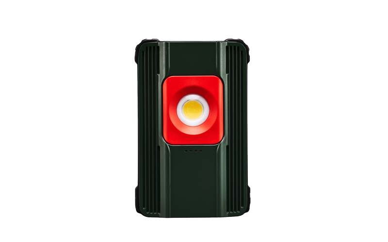
You must specify the correct hardware before touching any wires. Hardware evaluation prevents catastrophic failures and ensures long-term safety.
Load capacity matching stands as your top priority. You must calculate the total draw of your target Area Light. Ensure the switch amperage and wattage rating significantly exceeds this draw. Modern LED fixtures complicate this slightly. While LEDs draw minimal continuous power, their internal drivers pull a massive surge of electricity upon startup. We call this inrush current. A standard switch might handle the continuous load easily but weld its internal contacts shut during the initial LED surge. Always verify the switch holds an appropriate motor-load or LED-specific rating.
Environmental ratings dictate where you can safely install the equipment. Indoor installations typically require standard NEMA 1 enclosures. These boxes protect against basic dust and casual contact. Outdoor installations demand aggressive protection. You must use NEMA 3R or higher ratings. Employ weatherproof boxes and heavy-duty in-use covers. These bubble-style covers allow you to keep the switch protected even while operating it. Verify all components feature corrosion-resistant materials to withstand harsh weather.
Finally, determine your photocell bypass logic. If your fixture already has a photocell, you must decide how the new switch interacts with it. You can wire the switch in series with the sensor. In this setup, the switch acts as a master power disconnect. The switch must remain ON for the photocell to function normally. Alternatively, you can wire the switch to bypass the sensor entirely. This parallel configuration forces the light to turn on regardless of ambient sunlight. Choose the logic that best supports your daily operations.
Wiring requires extreme respect for electricity. Follow these specific phases to ensure a safe and successful implementation.
Locate your main electrical panel and identify the correct circuit breaker.
Execute Lockout/Tagout (LOTO) procedures. Apply a physical lock to the breaker panel so nobody can accidentally restore power while you work.
Approach the junction box and use a reliable non-contact voltage tester.
Test a known live circuit first to confirm your tester works. Test your target junction box to verify a zero-energy state. Test the known live circuit again. We call this the Live-Dead-Live method.
Identify your wire colors. Standard US 120V wiring uses black for hot, white for neutral, and green or bare copper for ground.
Route the incoming line power (black hot wire from the breaker) to one of the brass terminals on the switch.
Connect the outgoing load wire (black wire heading to the fixture) to the other brass terminal on the switch.
Splice the incoming and outgoing neutral wires (white) together using a properly sized wire nut. Standard mechanical switches do not interact with the neutral wire. Smart switches, however, usually require a dedicated neutral pigtail connected to this splice.
Connect all ground wires (green or bare) to the green grounding screw on the switch. If you use a metal junction box, bond the ground to the box as well. This maintains a continuous fault path to trip the breaker during a short circuit.
Open the fixture housing or the adjacent junction box.
Wire the remote receiver module directly inline with the incoming power.
Follow the manufacturer diagram carefully. Typically, you wire the receiver's line-in wires to the facility power, and the load-out wires directly to the fixture driver.
Tuck the receiver safely into the housing, ensuring no wires get pinched when sealing the cover.
Electrical modifications introduce specific risks. You must mitigate these through strict compliance and safety awareness.
Code compliance ensures your installation remains safe over decades. The NEC regulates box fill capacity to prevent dangerous overcrowding. Jamming too many wires into a small junction box traps heat. Heat degrades wire insulation and causes electrical fires. You must also match your wire gauge to the circuit breaker size. Use 14 AWG wire for 15-amp circuits. Use thicker 12 AWG wire for 20-amp circuits. Never mix lighter wire on a heavier breaker.
Weatherproofing failures represent the most common exterior installation defect. Water ingress destroys electronics rapidly. You must address this proactively. Apply silicone sealant around the top and sides of exterior surface-mounted boxes. Leave the bottom edge unsealed. This unsealed bottom acts as a weep hole, allowing internal condensation to escape. Always use correctly rated outdoor wire. UF-B (Underground Feeder) wire features a solid plastic jacket designed specifically to resist moisture and soil degradation.
You must understand your own professional liability. DIY electrical work carries inherent risks. You should escalate the project to a licensed electrician under specific conditions. If you encounter commercial 277V lighting systems, stop immediately. These high-voltage systems are lethal and require specialized commercial hardware. You should also hire a professional if you open a box and find confusing wiring, missing neutral wires, or degraded insulation. Modifying leased property or commercial facilities usually legally mandates a licensed electrician to maintain insurance liability coverage.
Moving from theory to execution requires organized planning. Take these concrete steps to prepare for your installation day.
Conduct a thorough site audit. Walk the exact path between your desired switch location and the light fixture. Measure the physical distance. This measurement dictates whether hardwiring is viable. Look for dense walls, metal structures, or major line-of-sight obstructions. These obstacles quickly rule out weak wireless systems.
Verify your existing infrastructure closely. Open the breaker panel and check the amperage size of the target circuit. Inspect the existing wire gauge at the fixture. Ensure your new materials match these existing parameters precisely.
Create a strict procurement checklist before driving to the supply house. Gathering materials in advance prevents frustrating mid-project delays.
Your selected switch type (Hardwired, Wireless Kit, or Smart Switch).
Appropriately rated weatherproof housing and in-use cover (if installing outdoors).
Correct gauge wire (14 AWG or 12 AWG) matching your circuit breaker.
Assorted wire nuts rated for the number of wires you plan to splice.
A high-quality non-contact voltage tester.
Outdoor-rated silicone sealant.
Wire strippers and insulated screwdrivers.
Adding a manual switch transforms your lighting from a passive fixture into an active operational asset. You gain absolute control over when and how your facility illuminates. This upgrade reduces unnecessary energy waste and drastically extends the mechanical lifespan of your circuit breakers.
While the fundamental wiring logic remains straightforward, your success hinges on careful planning. You must choose the correct solution category. A wireless retrofit saves days of labor, while a hardwired approach guarantees permanence. Whatever path you choose, you must strictly adhere to load calculations and environmental safety standards.
Audit your circuit load today. Map out your installation path to decide between hardwired or wireless hardware. Procure your code-compliant materials, execute your LOTO safety procedures, and confidently take control of your lighting environment.
A: Yes, you can wire a switch in parallel to bypass the photocell entirely. This forces the light on regardless of sunlight. Alternatively, you can wire it in series to act as a master override, meaning the switch must be on for the photocell to work.
A: Standard commercial wireless kits reach 100–150 feet outdoors. However, thick walls, metal siding, and heavy line-of-sight obstructions will significantly reduce this functional range. Always test the signal before permanently mounting the receiver.
A: Not necessarily. It depends entirely on the total amperage draw of the light compared to the existing load on the circuit. Always calculate the total continuous load and account for LED inrush current before splicing into an existing run.

